Cable size follows the 3% voltage drop limit
A 12V bank can afford 0.38V of drop, a 24V bank 0.77V and a 48V bank 1.44V before the cable loses 3% of the supply. That limit usually sets the cable size before the ampacity table does. Ampacity is the safety floor: the cable must not overheat. Voltage drop is the performance limit: the load must still see enough volts at the end of the run.
The 3% figure comes from the NEC informational note for branch circuits, which recommends no more than 3% drop on the branch and 5% total from the source to the load. Battery cables are not building branch circuits, but the same target works at 12V, 24V and 48V because the percentage scales with the system voltage.
| System | Nominal voltage | 3% drop limit | 5% drop limit |
|---|---|---|---|
| 12V | 12.8V | 0.38V | 0.64V |
| 24V | 25.6V | 0.77V | 1.28V |
| 48V | 48.0V | 1.44V | 2.40V |
The 48V row uses the nominal voltage on the 48V telecom datasheet (48V), not the 51.2V of a 16S pack. A 16S pack gets a little more headroom at the same percentage.
The DC voltage drop formula doubles the one-way length
The formula for a two-wire DC circuit is Vdrop = 2 x I x R x L. I is the current in amps, R is the conductor resistance in ohms per foot, and L is the one-way cable length in feet. The 2 accounts for the positive and negative conductors.
A 100A load on 10 ft of 2 AWG cable drops 2 x 100 x 0.000194 x 10 = 0.388V. That is 3.0% of 12.8V, right at the limit. The same cable at 20 ft drops 0.776V, which is 6.1% and too much for a 12V bank. On a 24V bank the same 20 ft run is 3.0%, and on a 48V bank it is 1.6%.
The formula assumes the cable is the only resistance in the circuit. Terminals, fuses, breakers, lugs and shunts add resistance. A poor crimp can add more drop than the cable. Use the formula to choose the cable, then measure the completed circuit under load.
Copper resistance and ampacity by gauge
The table uses copper conductors at 75°C. Resistance values are from NEC Chapter 9 Table 8. Ampacity values are from NEC Table 310.16 for “not more than three current-carrying conductors” in a raceway at 30°C ambient.
| AWG | Area | Resistance at 75°C | Ampacity at 75°C | Ampacity at 90°C |
|---|---|---|---|---|
| 10 AWG | 5.26 mm² | 1.24 Ω/1,000 ft | 35A | 40A |
| 8 AWG | 8.36 mm² | 0.778 Ω/1,000 ft | 50A | 55A |
| 6 AWG | 13.3 mm² | 0.491 Ω/1,000 ft | 65A | 75A |
| 4 AWG | 21.1 mm² | 0.308 Ω/1,000 ft | 85A | 95A |
| 2 AWG | 33.6 mm² | 0.194 Ω/1,000 ft | 115A | 130A |
| 1/0 AWG | 53.5 mm² | 0.122 Ω/1,000 ft | 150A | 170A |
| 2/0 AWG | 67.4 mm² | 0.0967 Ω/1,000 ft | 175A | 195A |
| 4/0 AWG | 107 mm² | 0.0608 Ω/1,000 ft | 230A | 260A |
Ampacity is not a suggestion. A 6 AWG cable is rated 65A at 75°C, so it cannot carry a 100A load. A 4 AWG cable is rated 85A, still below 100A. A 2 AWG cable is rated 115A and is the smallest gauge that carries 100A inside the table.
Maximum one-way length at 100A and 3% drop
The table solves the formula for L at 100A and a 3% drop limit. Double the length at 50A, halve it at 200A. The values are for one-way cable length, so a 10 ft row means 10 ft from battery to load, with 20 ft of copper in the circuit.
| Cable | 12V (0.38V) | 24V (0.77V) | 48V (1.44V) |
|---|---|---|---|
| 2 AWG | 9.9 ft | 19.8 ft | 37.1 ft |
| 1/0 AWG | 15.7 ft | 31.5 ft | 59.0 ft |
| 2/0 AWG | 19.9 ft | 39.7 ft | 74.5 ft |
| 4/0 AWG | 31.6 ft | 63.2 ft | 118 ft |
A 2 AWG cable is the minimum for 100A by ampacity, but it only supports a 9.9 ft run on 12V. Most RV and marine battery compartments have a one-way cable length of 6 ft to 12 ft, so 2 AWG is often just enough on 12V, and 1/0 gives margin. On 48V, 2 AWG covers 37.1 ft at 100A, which is why higher-voltage banks use thinner cable.
A 3kW inverter draws 260A at 12V and 70A at 48V
A 3,000W inverter at 90% efficiency pulls 260A from a 12.8V bank, 130A from a 25.6V bank and about 69A from a 48V bank. Current is power divided by voltage, with the inverter loss included. The lower the voltage, the thicker the cable and the larger the fuse.
| Load | 12V current | 24V current | 48V current |
|---|---|---|---|
| 1,000W | 87A | 43A | 22A |
| 2,000W | 174A | 87A | 43A |
| 3,000W | 260A | 130A | 69A |
| 5,000W | 434A | 217A | 109A |
At 12V, a single 4/0 cable is rated 230A, which is below the 260A load. Use two 2/0 cables in parallel (350A) or two 4/0 cables (460A). At 24V, a 1/0 cable (150A) covers 130A. At 48V, a 4 AWG cable (85A) covers 69A with margin. The cable size follows the current, not the inverter label.
LINEX bank current sets the cable and fuse floor
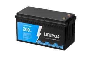
The LINEX 12V 100Ah, 24V 100Ah and 48V 100Ah packs all list a 100A maximum continuous discharge current. The 48V 150Ah pack lists 150A, and the 48V 200Ah pack lists 100A. The BMS sets the current limit, not the Ah rating.
| Model | Max continuous discharge | Minimum cable | One-way length at 3% | Fuse |
|---|---|---|---|---|
| 12V 100Ah | 100A | 2 AWG | 9.9 ft | 100A |
| 24V 100Ah | 100A | 2 AWG | 19.8 ft | 100A |
| 48V 100Ah | 100A | 2 AWG | 37.1 ft | 100A |
| 48V 150Ah | 150A | 1/0 AWG | 39.3 ft | 150A |
| 48V 200Ah | 100A | 2 AWG | 37.1 ft | 100A |
The length column is the maximum one-way run with the minimum cable. A longer run needs the next gauge up: 1/0 for the 100A models, 2/0 for the 150A model. The 48V 200Ah pack has a 100A limit even though its capacity is larger, so it uses the same cable as the 48V 100Ah pack.
Fuse the cable, not the battery
A 2 AWG cable with a 115A ampacity gets a 100A fuse, not a 200A fuse. The fuse protects the cable from a short circuit, so its rating should be at or below the cable ampacity and above the expected continuous current. A 1/0 cable with a 150A ampacity gets a 125A or 150A fuse.
The fuse also needs a DC voltage rating and an interrupt rating above the bank’s short-circuit current. A Class T fuse is common for 48V banks because it has a high interrupt rating in a small package. An MRBF fuse works for smaller 12V and 24V banks. A fuse holder that is not rated for DC will arc and fail to clear a fault.
Every parallel battery needs its own fuse. A 200A fuse on the combined bus does not protect a 100Ah battery that can feed a fault through its own cables. Equal cable lengths between parallel batteries keep the current split even.
What to write on the build sheet
Write six items on the build sheet: system voltage, maximum continuous current, one-way cable length, cable gauge, fuse rating and fuse type. Add the lug size, torque and the measured voltage drop at full load. A build sheet that only says “2 AWG” does not say whether the cable is long enough for the load.
For a 12V 100Ah bank, a 3 ft one-way run at 100A needs 2 AWG and a 100A fuse. For a 48V 100Ah bank, the same 3 ft run at 100A also needs 2 AWG, but the cable can run 37 ft before the 3% limit. The higher voltage buys length, not a smaller cable at the same current.
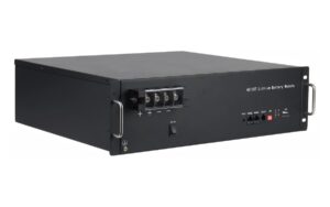
The 24V lithium battery line and 48V lithium battery line list the models and current limits. The 12V 100Ah battery page gives the 100A continuous limit and the 8.8V to 14.6V operating range. The 48V 100Ah telecom battery page lists the 100A charge and discharge limit, the 40.5V cutoff and the 51.0V float voltage. The battery voltage charts give the rest and charging voltages used in the examples. The Ah to kWh calculator converts the bank size to energy if the load is listed in kWh.
Check the voltage drop after assembly. Put a known load on the bank, measure at the battery terminals and at the load, and compare the difference to the 3% target. A crimp that looked fine can show up as 0.5V of drop at 100A.
Frequently asked questions
A 12V 100Ah battery with a 100A BMS needs 2 AWG for a one-way run up to about 10 ft at 3% drop. Use 1/0 for runs up to 16 ft. The fuse should be 100A and rated for DC.
A 4 AWG cable is rated 85A at 75°C, so it is below the 100A continuous limit of the 48V 100Ah battery. Use 2 AWG, which is rated 115A and supports a 37 ft one-way run at 3% drop.
Higher voltage reduces current for the same power, so the cable can be thinner for a given load. The cable still has to meet the battery’s maximum current and the fuse rating. A 48V 150Ah battery needs 1/0 cable for its 150A limit even though the load may draw less.
The fuse protects the cable, so its rating should be at or below the cable ampacity. A 2 AWG cable with a 115A ampacity gets a 100A fuse. A 200A fuse on 2 AWG cable leaves the cable unprotected.
Measure the voltage at the battery terminals and at the load while the load is running. Subtract the load voltage from the battery voltage. Divide the difference by the battery voltage and multiply by 100 to get the percentage. Do this at the highest expected load.
The formula uses one-way length and multiplies by 2 for the positive and negative cables. If the one-way run is 10 ft, the circuit has 20 ft of copper. Keep the one-way number in the table and let the formula handle the return path.
Sources: NFPA 70 National Electrical Code 2023, Table 310.16 ampacities and Chapter 9 Table 8 conductor resistance (checked 2026-11-13); NFPA 70 210.19(A) Informational Note No. 4, 3% branch-circuit and 5% total voltage drop (checked 2026-11-13); Cerrowire ampacity chart, 75°C and 90°C copper columns (checked 2026-11-13); LINEX 12V 100Ah datasheet (12.8V, 100Ah, 1,280Wh, 100A continuous, 8.8V to 14.6V, 0°C to 50°C charge, -20°C to 60°C discharge, 6,000 cycles at 25°C and 80% DoD, checked 2026-11-13); LINEX 24V 100Ah datasheet (25.6V, 100Ah, 2,560Wh, 100A continuous, 17.6V to 29.2V, checked 2026-11-13); LINEX 48V 100Ah datasheet (48V, 100Ah, 4.8kWh, 100A charge and discharge, 40.5V cutoff, 51.0V float, 53.3V equalization, 43kg, 3U, checked 2026-11-13); LINEX 48V 150Ah datasheet (48V, 150Ah, 7.2kWh, 150A charge and discharge, 60kg, checked 2026-11-13); LINEX 48V 200Ah datasheet (48V, 200Ah, 9.6kWh, 100A charge and discharge, 78kg, checked 2026-11-13). Last updated 2026-11-13.