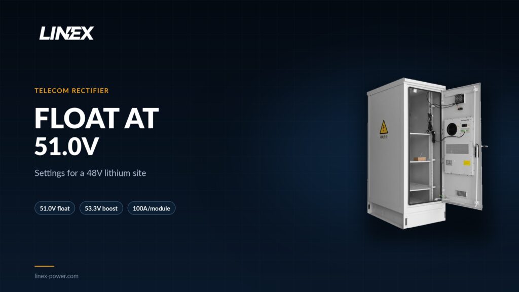
Float voltage drops from 54.0V to 51.0V
A 48V lead-acid plant uses 24 cells at 2V each, and a float of 2.25V per cell puts the bus at 54.0V. A LINEX 48V LiFePO4 module uses 15 cells at 3.2V each, and its datasheet float is 3.40V per cell, or 51.0V. The 3V gap is not a fine trim: 54.0V across 15 lithium cells is 3.60V per cell, above the 3.55V boost specification.
| Parameter | 24-cell VRLA plant | 15S LiFePO4 module |
|---|---|---|
| Cells in series | 24 x 2V | 15 x 3.2V |
| Float voltage | 54.0V (2.25V/cell) | 51.0V (3.40V/cell) |
| Equalize or boost | 56.4V (2.35V/cell) | 53.3V (3.55V/cell) |
| Low-voltage disconnect | 43.2V typical (1.80V/cell) | Above 40.5V cutoff (2.70V/cell) |
| Temperature compensation | About -3mV/°C/cell | Off |
| Charge current limit | 0.1C to 0.2C | 100A per 100Ah module |
The rectifier will hold whatever setpoint it is given. If the lead-acid float remains at 54.0V, the lithium pack sits 0.20V per cell above its float voltage and 0.05V above its boost voltage for as long as the site has AC power. That is a continuous overcharge, not a brief absorption stage. Change the float setpoint before the battery is connected.
Equalize becomes a 53.3V boost, not a 56.4V cycle
Lead-acid plants run an equalize cycle at 56.4V to stir the electrolyte and balance cells. A LiFePO4 module does not need that cycle. Its datasheet lists 53.3V as the equalization charge voltage, which is a short boost, not a lead-acid equalize. An automatic timer left at 56.4V applies 3.76V per cell to a 15S pack.
Set the equalize voltage to 53.3V and disable the automatic timer. If the rectifier only supports a fixed equalize cycle, turn equalize off and let the BMS balance the cells. Check the same setting on any solar controller or DC-DC charger at the site, because a second charging source can undo the rectifier setting.
Current limit follows the module count
The 48V 100Ah module accepts 100A charge and 100A discharge at 25°C. A 200A or 300A rectifier bay can exceed that when the site load is light and the battery is deeply discharged. Set the rectifier current limit to the sum of the module ratings, not to the old lead-acid C-rate.
| Module | Nominal energy | Max charge | Max discharge | Weight |
|---|---|---|---|---|
| 48V 50Ah | 2.4kWh | 50A | 50A | 29kg |
| 48V 100Ah | 4.8kWh | 100A | 100A | 43kg |
| 48V 150Ah | 7.2kWh | 150A | 150A | 60kg |
| 48V 200Ah | 9.6kWh | 100A | 100A | 78kg |
At 51V, 100A is about 5.1kW of charge power. Two 100Ah modules accept 200A, and three accept 300A. The 150Ah module accepts 150A, while the 200Ah module stays at 100A, so a larger case does not always mean a faster charge. A 200Ah module holds more energy at the same current, which stretches the recharge time rather than shortening it.
Temperature compensation and the low-voltage disconnect
A lead-acid rectifier shifts its output with temperature, usually by about -3mV per °C per cell. The LiFePO4 BMS manages cell voltage itself, so temperature compensation must be off. A compensated rectifier raises the bus in cold weather, which pushes the pack further above 51.0V when the cells are already harder to charge.
The low-voltage disconnect needs the same review. A lead-acid site often treats 43.2V as empty, while the LiFePO4 module can run to 40.5V before the BMS opens. Keep the site disconnect above 40.5V so the plant drops the load before the BMS does, and prove the setting with a discharge test. If the disconnect stays at 43.2V, the site gives up some usable capacity but keeps a margin.
Commissioning sequence for the swap
Commissioning starts before the battery arrives. Record the rectifier model and check that its float adjustment reaches 51.0V and its boost adjustment reaches 53.3V. A plant that bottoms out at 53.5V cannot hold the pack at its datasheet float, and no battery setting will fix that.
| Step | Check | Target |
|---|---|---|
| 1 | Rectifier float range | 51.0V reachable |
| 2 | Boost or equalize setting | 53.3V, automatic timer off |
| 3 | Current limit | 100A per 100Ah module |
| 4 | Temperature compensation | Off |
| 5 | Low-voltage disconnect | Above 40.5V |
| 6 | BMS communication | RS485 or RS232 mapped to the site controller |
| 7 | Discharge test | Site disconnect trips before the BMS |
Measure the float voltage at the battery terminals, not only on the rectifier display. A loose fuse holder or undersized cable drops voltage under charge, and the pack then sits below the setpoint even when the rectifier reads correctly. Record the module serial numbers and the discharge result in the site file.
Older rectifiers and staged upgrades
Some older plants have a narrow adjustment range or a fixed equalize cycle. A rectifier that cannot reach 51.0V float is a mismatch, not a battery fault. Replace the rectifier, or use a smart 48V module with a built-in DC-DC converter for a staged upgrade. The smart version adds CAN communication and a boost to 57V for hybrid sites that still run a lead-acid string.
A hybrid bus needs an engineering review. The two chemistries have different charge profiles, so they cannot share a rectifier without controls that separate them. The simpler path is a full replacement with the rectifier reset to the lithium profile.
Where the 48V modules fit
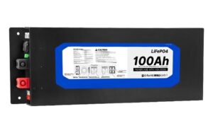
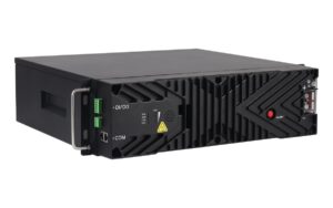
The 48V 100Ah module is 4.8kWh, 100A continuous, 43kg and 3U in a 19-inch rack. It replaces a 150Ah VRLA string in a typical telecom site. The 48V 200Ah module is 9.6kWh, 100A continuous and 78kg in a 482 x 610 x 178mm case. Both use 51.0V float, 53.3V boost and 40.5V cutoff. For the full range, see the 48V lithium battery line. For site sizing, see the telecom remote sites guide. The 48V 100Ah telecom battery and 48V 200Ah telecom battery pages list the full specifications, and the 48V telecom site retrofit guide covers the mechanical swap.
Frequently asked questions
No. A 15S 48V LiFePO4 module floats at 51.0V. At 54.0V, each cell sits at 3.60V, above the 3.55V boost specification. Lower the float setpoint before connecting the battery.
The module lists 53.3V as its equalization voltage, so an automatic 56.4V lead-acid equalize cycle must be disabled or reset. A 56.4V cycle applies 3.76V per cell to a 15S pack.
Set 100A per 100Ah module. Two modules take 200A, and three take 300A. The 150Ah module takes 150A, while the 200Ah module stays at 100A.
No. Turn it off. The BMS manages cell voltage, and a compensated rectifier can push the bus above 51.0V in cold weather.
Keep the site disconnect above the 40.5V battery cutoff so the plant drops the load before the BMS opens. Confirm the setting with a discharge test.
Sources: LINEX 48V 100Ah telecom battery page (4.8kWh, 100A charge and discharge, 43kg, 3U, 53.3V equalize, 51.0V float, 40.5V cutoff, 6,000 cycles, checked 2026-11-21); LINEX 48V 200Ah telecom battery page (9.6kWh, 100A, 78kg, 482 x 610 x 178mm, checked 2026-11-21); LINEX 48V lithium battery range (50Ah to 200Ah, current ratings, smart DC-DC boost to 57V, checked 2026-11-21); LINEX 48V telecom site retrofit guide (24-cell lead-acid float 54.0V and equalize 56.4V, 15S LiFePO4 float 51.0V and equalize 53.3V, LVD 43.2V, temperature coefficient, checked 2026-11-21); LINEX telecom remote sites page (site load and backup table, checked 2026-11-21); LINEX 48V telecom battery selection guide (rectifier compatibility checks, checked 2026-11-21); LINEX battery voltage charts (16S versus 15S charge settings, checked 2026-11-21); Battery University BU-403 (lead-acid temperature coefficient of -3mV/°C/cell, checked 2026-11-21). Last updated 2026-11-21.